Design of work holding fixture for 3 axis machining of bike stem (operation 2)

Bike stem
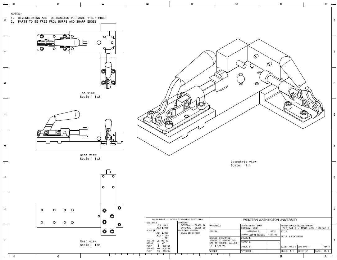
Assembly
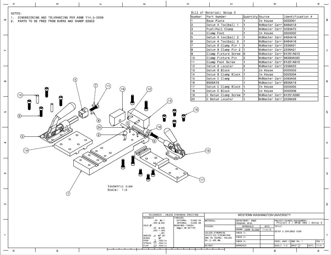
Exploded view
Locating and clamping location methodology:
The fixture created for setup 2 was as deterministic as possible while allowing for sufficient forces to be applied to the part in order to maintain static equilibrium while machining. The A datum is the most deterministic, being supported by three spheres allows the reaction forces to be pinpointed almost exactly. The B datum is the second most deterministic. It is located using two 5mm diameter flat pins. While this creates a possibility for contact on three points across either pin, it is decidedly more deterministic than using the round edge of a pin spanning the length of the datum. The method of two flats limits the contact to the area on either of the pins rather than anywhere along the length of a round pin. The C datum is the least deterministic of the three datums. It is located using a single 8mm diameter flat. This means that there are three points of contact on the C datum, however, by using the smallest dimeter possible to withstand the clamping force, it is as deterministic as it can be.
One internal debate regarding determinism I grappled with when arriving at my solution was the decidedly indeterministic nature of a build up fixture. With multiple interfacing parts, tolerancing error stacks up. Because of this, all interfaces must be machined to a high tolerance to account for this. At a minimum, the interfacing parts should have a flatness that allows the sum of the tolerances across the interfaces to equal to or less than the required tolerances for the fixture. Despite this downfall of a build up fixture, creating it in this manor allowed for better clamping of the part, improved ease of use, and a cheaper fixture than could be created using vices.
assumptions about magnitude and direction of machining forces:
Due to the profiles being milled in this setup, the machining forces will be primarily applied in the X & Y (parallel with the baseplate) with relatively little force in Z. It was decided that any translation in Z would be done off the part, allowing the tool to enter the stock tangentially rather than axially. This is the reason that spheres could be used to locate the A datum. Using Hertzian calculations, it was found that in order to withstand machining forces of 2500N or approximately 562lb, a sphere of radius 4.5” must be used. However, due to the assumption stated above, datum A was able to be located deterministically. In the X and Y directions, the locators were selected using Hertzian calculations using a force equal to that applied by the Push/Pull clamps. All calculations were done assuming the part to be made of 7075 T-73 Aluminum and the locators being made of hardened tool steel.
ease of use:
The fixturing for step two was specifically designed with ease of use in mind. Datums are located in order of their significance (A, then B, then C). After the part has been located, it is held downward (in the Z direction against the A datum locators) and pushed sideways (into the B and C datum locators) by hand as the push/pull clamp is closed clamping the part against the B datum locators. Next, while applying force by hand only in the Z direction, the push pull clamp for datum C is then closed. This simple process allows for quick cycle times and repeatable location of the part. Once the preform has been machined into the post-form, it can be released from the fixture simply by flipping open the two clamps.
Comparison of design of gages vs. design of machining fixtures:
The design of gages and machining fixtures are both similar and different in various ways. To start with the similarities, properly locating datums is essential to the proper operation of the two. Both tools base their effectiveness on the tools ability to allow the parts datum to line up with where it is expected to be. In terms of common challenges, considering determinism is a very difficult task. It is impossible to be completely deterministic but working within the bounds of allowable error is a tremendous challenge that presents itself. One must balance determinism of the tool with its practicality.
In terms of differences between the two assignments, I feel that gage design is more focused on precision and accuracy, whereas machine fixturing is about getting away with lack of those two metrics while staying within the bound of the finished part. Gaging and machine fixturing go hand in hand, because proper machine fixturing, and machining allows parts to properly pass gaging, while gaging is a check to ensure that machine fixturing is doing its job to specification.
As far as the amount of work, I think that machine fixturing design is more difficult, however, in terms of conceptualization of the task, as well as assurance that tolerance values are correct throughout the tool, gage design is more difficult. I feel that the amount of time that goes into figuring our how exactly to build a machine fixture that will properly complete its task while remaining sufficiently deterministic is greater. On the other hand, being able to properly call out tolerances, and design a gage that is simple to use while meeting the needs of practical use is more difficult. All things considered, I think designing either is equally difficult, just for different reasons.